Breaking News
Main Menu
Gate Drive Circuit For Mosfet
пятница 14 декабря admin 2
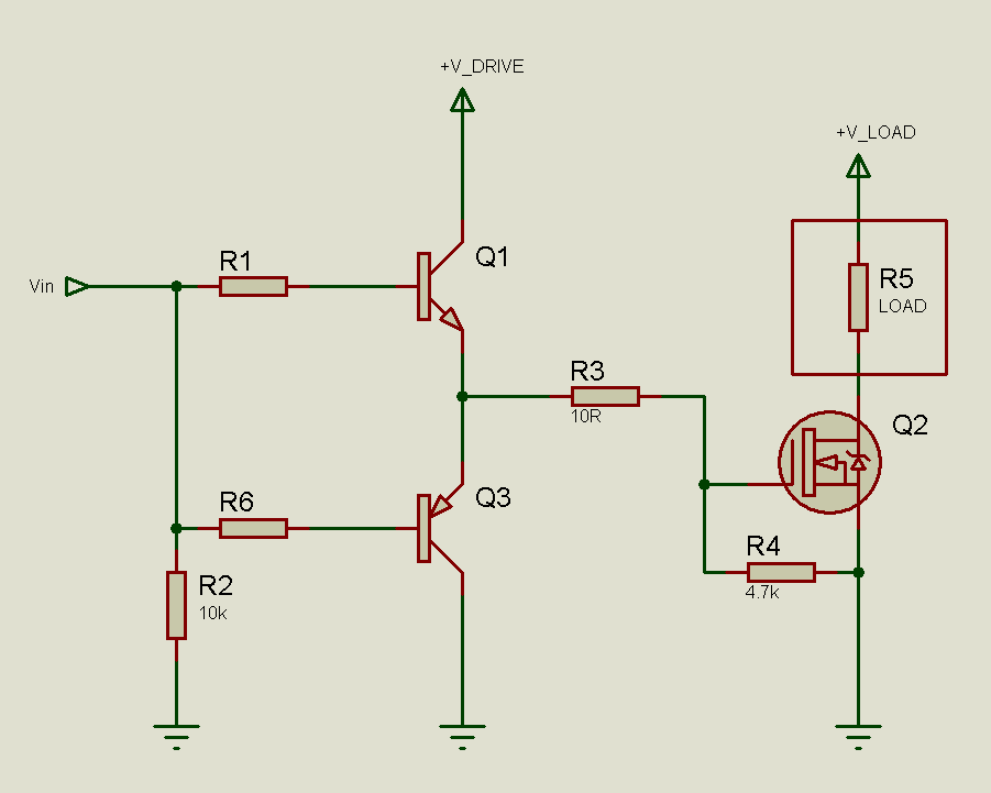
Download c compiler for windows 10. Designers unfamiliar with MOSFET or IGBT input characteristics begin drive circuit design by determining component values based on the gate-to-source, or input, capacitance listed on the data sheet. RC value based on the gate-to-source capacitance normally lead to a gate drive that is hopelessly inadequate. Ally puts in series with the Gate of a MOSFET to control the turn-on and turn-off speed of the MOSFET. (3A) Symbol and equivalent circuit of a MOSFET Symbol of N-Channel MOSFET D G S G CGD CGS RG D S CDS int RDS(on) VGS V DS Fig. (3B) C variation Vwith respect to DS V =DS CGD CGD CGD h l GD Fig (4A) A MOSFET bein g turned on by a driver.
Can anyone please explain (or suggest online reading that explain) what factors have to be taken into consideration when driving a power MOSFET with a PWM signal for power control such as motor speed or power supplies, especially at the gate? I understand that a MOSFET gate is essentially an open circuit at low frequencies, but at higher frequencies, capacitive effects modify the necessary drive power and switching times (and possibly other things). Simple hobby-type circuits often drive the gate with resistive coupling from an opamp or something with a similar output, but more sophisticated circuits usually include capacitors, diodes and inductors between driver and MOSFET.
Please help me understand the principles. Can anyone please explain (or suggest online reading that explain) what factors have to be taken into consideration when driving a power MOSFET with a PWM signal for power control such as motor speed or power supplies, especially at the gate? I understand that a MOSFET gate is essentially an open circuit at low frequencies, but at higher frequencies, capacitive effects modify the necessary drive power and switching times (and possibly other things). Simple hobby-type circuits often drive the gate with resistive coupling from an opamp or something with a similar output, but more sophisticated circuits usually include capacitors, diodes and inductors between driver and MOSFET. Please help me understand the principles.

Can anyone please explain (or suggest online reading that explain) what factors have to be taken into consideration when driving a power MOSFET with a PWM signal for power control such as motor speed or power supplies, especially at the gate? I understand that a MOSFET gate is essentially an open circuit at low frequencies, but at higher frequencies, capacitive effects modify the necessary drive power and switching times (and possibly other things). Simple hobby-type circuits often drive the gate with resistive coupling from an opamp or something with a similar output, but more sophisticated circuits usually include capacitors, diodes and inductors between driver and MOSFET. Bonaire shore diving made easy pdf reader. Please help me understand the principles.